- Powder Metallurgy (PM) technology
-
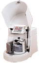
Fig.3 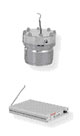
Fig 2 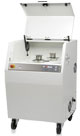
Fig 1 - Mechanical
Alloying (MA)
Represents one of PM routes to process: composite powders, micro-sized or nano-sized or nano-structured powder particles depending on the technological parameters: powder mixture / milling balls ratio, milling balls size, atmosphere (inert, oxidation, reductive), ambience (dry/wet conditions), rotation speed, milling mode (friction/stroke), milling time. Gas pressure and temperature developed inside the bowl mill during MA process are monitored by GTM device (Fig.2).
(Photos: planetary ball mills and complementary device, Fritsch, Germany, Fig.1. Pulverisette 4 ball mill and Fig.3. Pulverisette 6 ball mill; University of Craiova, Faculty of Mechanics, Department of Engineering and Management of Technological Systems) - MEDium
Pressure Injection MOLDing (MEDPIMOLD)
Represents a new injection system to process small and complex shaped parts in metallic, ceramic or composite materials, for small and large scale production. The feeding assembly (fig.1) is connected to a vacuum system (fig.2), providing an injection pressure of 7...10 MPa. Bulk feedstock (fig.3), heated up at max. 100ºC, is absorbed through the feeding system up to the small metallic die (fig.4).
(Photo: MEDPIMOLD GOCERAM AB, Sweden; Univ. of Craiova, Faculty of Mechanics, dept. of I.M.S.T.) -
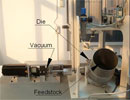
Fig 1 -
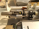
Fig 2 -
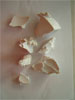
Fig 3 -
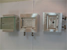
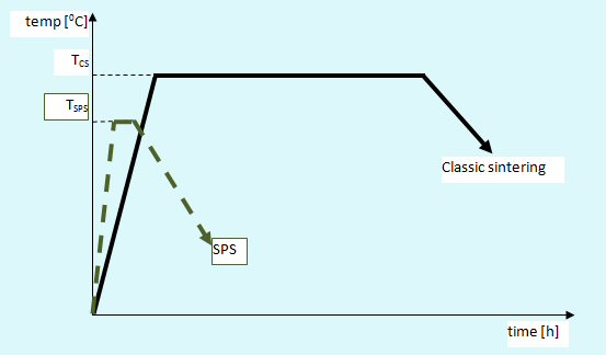
Fig 4 - Spark
Plasma Sintering (SPS)
Represents an advanced sintering route dedicated to ceramic parts as well as metallic and composite products. Plasma heating system provides much lower sintering temperature (Tsps) and time (about minutes) than the classic sintering route, fig.1. Because of these great advantages, SPS allows nanostructures elaboration, too. One of group collaborators, National Institute for Research and Development for Technical Physics, Iasi, Romania, www.phys-iasi.ro, uses (SPS)-FCT-(FAST) HPD5 equipment, working under the following terms: max. current intensity Imax. = 20 kA; max. sintering temperature 2400ºC (working temperature 2200ºC); sintering atmosphere: vacuum; max. load: 50kN, for fundamental and applicative research in advanced materials elaboration.
- Microwave
Sintering (MWS)
Represents an advanced sintering route dedicated especially to ceramic parts as well as metallic and composite products. The electromagnetic field of high frequency (2,45 GHz) converts into thermal energy and heats the green compacts. The sintering process develops at lower temperatures (Tmvs < Tcs) and shorter sintering times than in the case of the conventional sintering, fig.1. Because of these great advantages, MWS allows nanostructures elaboration, too.
(Photo: Fig.2 MUEGGE MWS equipment, Germany; Univ. of Craiova, Faculty of Mechanics department of Engineering and Management of Technological Systems)
(Photo: Fig.3 Multi-mode MW heating equipment designed at Univ. of Craiova; Faculty of Mechanics department of Engineering and Management of Technological Systems)
-
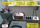
Fig 2 -
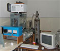
Fig 3 - Two
Steps Sintering (tss)
Represents a modern route to process advanced sintered structures: ceramics, composites (metallics/ceramics) and nanostructured materials, too. tss process is based on two steps, fig.1. The 1st steps consists in heating the green compacts up to a temperature, T1-tss, nearby the conventional sintering temperature and keep it for a very short time (few minutes) just for difussion reactions ignition. Then, the 2nd steps develops by quick temperature decreasing up to T2-tss followed by a long dwell time for material densification. tss could be developed in inert, oxidation or reductive atmosphere
(NABERTHERM furnace, Italy; Univ. of Craiova, Department of Physics)
- Post-Sintering processing
- Cutting
processes (high speed milling, turning and drilling)
are machining processes developed at a micro scale focused especially on machining of MEMS (Micro-Electro-Mechanical-Systems). Among these cutting processes high speed milling was actually introduced as complementary technology for rapid prototyping. High speed milling combines high spindle speeds with increased feed rates. These results in a high chipforming rate and lower milling forces, producing an improved surface quality and closer tolerances The high speed milling process is intended to be applied by tiara-C group mainly on nanostructured biocomposite materials with hydroxiapatite matrix reinforced with metallic powder metals such as Ti. The high speed milling is performed on a vertical CNC centre FADAL, VMC 2216 FX
Fig.1 (Univ. of Craiova, Faculty of Mechanics department of Engineering and Management of Technological Systems)
Fig.2 a) Spare part for a MEMS device
Fig.2 b) Flank wear of an end ball mill used for machining of Ti reinforced composite -
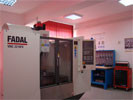
Fig 1 -
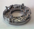
Fig 2a -

Fig 2b - Laser
Micromachining (LM)
is an advanced cutting/assembling/coating process, recommended for those materials which are difficult to be processed by conventional processes (drilling, milling etc.), (View Movie). The necessity of LM process is requested by:
—the non-uniform geometrical feature of the product;
—the material structure and properties not allowing the common machining techniques. It could be: high hardness, high porosity, brittleness, nanocrystalline grains in the material structure etc.
LM processing is applied by tiara-C group especially in the case of PM nanostructured biocomposites based on hydroxyapatite, reinforced by metallic powder particles on laser source KLS246 fig.1. The macroscopical aspect of the coarse surface of the laser machined surface is presented in figure 2.
(LASAG laser source KLS246, Switzerland; Univ. of Craiova, Faculty of Mechanics department of Engineering and Management of Technological Systems)
Fig. 1 (LASAG laser source KLS246, Switzerland; Univ. of Craiova, Faculty of Engineering and Management of Technological Systems endowment
Fig. 2 LM-ed surface with three different cutting regimes (X8 magnification) of HAP/Ti biocomposites: a)Ra=18.2 µm in R1 regime: voltage = 250 V; pulse frequency = 50 Hz; pulse duration = 0.35 ms; average power = 41 W b)Ra=5.2 µm in R5 regime: voltage = 280 V; pulse frequency = 50 Hz; pulse duration = 0.35 ms; average power = 43 W c)Ra=5 µm in R7 regime: voltage = 310 V; pulse frequency = 50 Hz; pulse duration = 0.35 ms; average power = 58,5 W 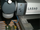
Fig 1 -
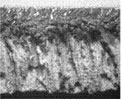
Fig 2a -
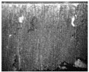
Fig 2b -
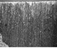
Fig 2c - Materials
- Metal
Matrix Composites (MMCs)
are one of the main materials concepts that tiara-C group deals with. The MMCs already developed by tiara-C members and collaborators are:
lightweight MMCs:
—Al-based composite materials, fig.1, with high friction coefficient for automotive and aerospace applications, Prof. Oana GINGU
—Al-based composite materials with low friction coefficient for automotive and aerospace applications, Assoc.Prof. Gabriela SIMA
—Al-based composite foams, fig.2, for sports components, Assoc. Prof. Gabriel MANGRA
other MMCs:
—W-based MMCs, fig.3, for electrical applications, Assoc. Prof. Ileana PASCU
Fig.1 Al/SiC composite powder particles processed by MA route, [O. Gingu, M. Mangra, R. L. Orban, In-situ production of Al/SiCp composite by laser deposition technology, Journal of Materials Processing Technology, Volumes 89-90, 19 May 1999, 187-190]
Fig.2: Infiltrated composite foam covering the table tennis racket [G.I. Mangra, O. Gingu, Processing of the metallic foams coverings for the tennis table rackets, Procedia Engineering, 2009 (in press)]
Fig.3 W/Cu sintered composite [C.I. Pascu, Al. Stanimir, I. Vida-Simiti, Research on the Manufacture of Some Tungsten-Copper Composite after Vacuum Sintering, "Materials Science Forum" Journal, edited by Trans. Tech. Publications Ltd, Switzerland, 2010] -
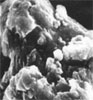
Fig 1 -
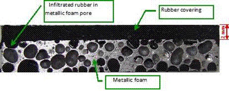
Fig 2 -
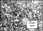
Fig 3 - Ceramic
Matrix Composites (CMCs)
are one of the main materials concepts that tiara-C group deals with. The CMCs already developed by tiaraC members are lightweight CMCs:
—Hydroxyapatite-based nanostructured composites for cortical bone grafting, Prof. Oana GINGU, patent no.A/00318/2010 (to be published)
—Hydroxyapatite-based nanostructured composites for trabecular bone grafting, Assoc.Prof. Ileana PASCU, patent no. A/00317/2010 (to be published) - Characterization
- Particle
size distribution
is an important parameter to detect concerning powder particles, especially in the case submicronic powders. Counting, sizing and visualising nanoparticles by light scatter or fluorescent emissions are relevant features to design structural advanced materials for engineered and biomedical applications. tiara-C group performed measurements and imaging on particle size distribution using the following equipments:
Fig.1: NANOSIGHT LM 10 equipment; Univ. of Craiova, Faculty of of Mechanics department of Engineering and Management of Technological Systems;
Fig.2: 90 Plus Particle Size Analyzer BROOKHAVEN equipment; Univ. of Craiova; Faculty of Mechanics department of Engineering and Management of Technological Systems -
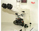
Fig 1 -
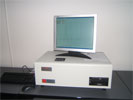
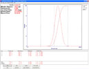
Fig 2 - Thermal
properties
of the composite materials are different from the components ones. On the other hand, composites' processing from composite powders (made by Mechanical Alloying or other routes) determines major changes of their thermal properties. Also, nanostructured or nano-sized (composite/metallic/ceramic) powders have different thermal properties than the same "conventional" particles (micronic size or microstructured). Thus, it is critical to determine thermal properties of new powder particles processed by PM routes. The new critical points may have major influence on the values of the composites' synthesis temperatures.
tiara-C group is able to determine the thermal properties of the advanced materials researched on the "Diamond" Differential / Thermogravimetric Analyser ( from PerkinElmer Instruments; Univ. of Craiova, Department of Physics). - Structural
Analysis
of the advanced composites developed by tiara-C group regards:
imaging of processed materials by:
—Optical Microscopy (on inverted metallographic microscope Eclipse MA 100, Nikon Corporation, Japan, with NIS-Elements imaging software, version 3.03; Univ. of Craiova, Faculty of Engineering and Management of Technological Systems endowment), fig.1;
—Electronic Microscopy, fig.2;
—Atomic Force Microscopy (Univ. of Craiova, Faculty of Physics endowment)
qualitative analysis by:
X Rays Diffraction (Univ. of Craiova, Faculty of Physics endowment)
Fig.1 Hidroxyapatite - based biocomposites reinforced by Ti powder particles, conventionally sintered in chamber furnace (OM image, 750X)
Fig.2 Hidroxyapatite - based biocomposites reinforced by Ti powder particles sintered by Spark Plasma Sintering (SPS) route (SEM image) 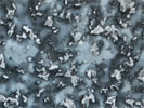
Fig 1 -
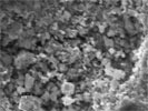
Fig 2 - The
surface quality evaluation
of the advanced composites developed by tiara-C group is performed by the MultiGage equipment developed by TESA Technology, fig.1. (Univ. of Craiova, Faculty of Mechanics endowment). It is equipped with 2 spherical tracers: one of 15 mm diameter for gauging and one of 6 mm, in ruby, for measurements. According to ISO10360-2, the measurement precision is 5 µm, the measuring head is TESASTAR-p/ -mp and the software is Micro-Gage, fig.2.
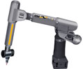
Fig 1 -

Fig 2 - Mechanical
testing
performed by tiara-C group on different materials classes including composites are:
—hardness and micro-hardness tested by NAMICON equipment, fig.1, testing HV0,01 ... HV1, with analogical microscope and video control of the image (Univ. of Craiova, Faculty of of Mechanics department of Engineering and Management of Technological Systems);
—universal mechanical tests by A009 electromechanical-computerized 100kN testing machine, fig. 2, connected to TCSoft2004Plus software, able to control all function of universal machine: diagnostic, calibration, handling, to create and select the operating mode, test execution, data logging (max force, breaking load, final length, specimen area and testing speed), data storage in a data base, displays the stress-strain curve in actual time with automatic range of plot, export the data in the format configured for statistics evaluations and print a complete report of test (Univ. of Craiova, Faculty of Engineering and Management of Technological Systems endowment)
Fig.1 NAMICON hardness testing equipment
Fig.2 A009 electromechanical-computerized 100kN testing machine -
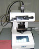
Fig 1 -
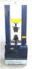
Fig 2 - Tribological
testing and wear behaviour
performed by tiara-C group on different materials classes including composites are:
evaluation of the processed materials by tiara-C group are performed on the tribometer TRB 01-02541 (CSM Instruments SA, Switzerland), fig.1, (View Movie), with linear reciprocating module, equipped by InstrumX software, version 2.5A. The main characteristics of the tribometer are: max. torque = 450 Nmm; max. load = 46 N; frequency up to 1,6 Hz; linear speed range = (0,3 - 500) mm/s; stroke range = 60 mm; sliding time up to 40 days with acquisition rate of 10 Hz; Windows 95/NT compatible software with post calculation possibilities (Hertzian pressure, static partner and sample wear rate) (Univ. of Craiova, Faculty of Engineering and Management of Technological Systems endowment). Fig.2: morphological aspect of a worn track in SEM image version. The worn track profile is determined by the profilometer Surtronic 25 (M112/3522-01), Taylor Hobson Precision (England) equipped by TalyProfile Silver software for the technical determinations (View Movie). The technical parameters are: roughness type, Ra; cut-off = 0,8mm; evaluation length = 2...4 mm; range = 100 mm (Univ. of Craiova, Faculty of of Mechanics department of Engineering and Management of Technological Systems ).
Fig.1 Tribometer TRB 01-02541 (CSM Instruments SA, Switzerland
Fig.2 Worn track morphology of hydroxyapatite-based reinforced by Ti powder particles, processed by Two Steps Sintering route, wear tested in dry friction conditions on TRB tribometer (SEM imaging courtesy of Politecnico di Torino University, Italy) -
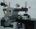
Fig 1 -
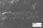
Fig 2 -
Biocompatibility Testing Concerning the biocompatibility testing of the biocomposites developed by tiara-C collaborators, the main tests are performed as follows:
—in-vitro conditions, coordinated by The University of Medicine and Farmacy - Craiova, Faculty of Farmacy, Prof. Johny NEAMTU
—in-vivo conditions, coordinated by The University of Medicine and Farmacy "Victor Babes", Timisoara, Prof. Mihai IONAC and Ph.D. student Roxana VOISAN -
Biomechanical Testing Concerning the biomechanical testing of the biocomposites developed by tiara-C collaborators, the main tests are performed at the Emergency Clinical Hospital "Bagdasar-Arseni", Bucharest, coordinated by Prof. Radu Mircea GORGAN